

Tower Subway under the Thames River, interior of completed tunnel, 1887.
Tunnel Engineering – A Museum Treatment by Robert M. Vogel is a brief history of engineered transportation tunnels published in 1964. The booklet was part of series that accompanied scaled model displays illustrating the advances in tunneling primarily in the 19th century. The short thirty-six page bulletin focuses on how modern engineering design evolved as applied to hard rock and soft ground tunnels used for transportation. Download the PDF document of Tunnel Engineering at the end of the post.
Tunnel engineering booklet
I found this little booklet, published by the Smithsonian Institution in 1964, at an antiquarian book fair in Sacramento. It caught my attention because Vogel devotes a whole section to the building of the Hoosac tunnel in northwest Massachusetts. As my son had just committed to attend Williams College a short distance from the western entrance of the Hoosac Tunnel I thought it would be good historical background for our trip to Williamstown and the construction of tunnels is pretty interesting.
Compressed history of tunnel construction
Tunnel Engineering contains many pictures of the scaled tunnels and the equipment employed during the construction along with illustrations created at the time the tunnels were being built. There is no author section or biography, but Vogel is at a minimum a true historian and very possibly an engineer himself. While Vogel doesn’t overwhelm the reader with engineering language, Tunnel Engineering isn’t written at a fifth grade level either. Consequently, the text can be a little dense for the lay man, but is perfectly suited for budding engineers.
19th century tunnel engineering advances, failures
A real strength of Tunnel Engineering is it traces the engineering failures and advances of constructing the tunnels. Part of the progress was due to improved tools such the increased explosive power of nitroglycerin over black powder which the builders of the Hoosac tunnel started with. Vogel also details the mechanical engineering evolution of the different machines the engineers developed to address various problems encountered underground.
Air pressure propels subway passenger car
Perhaps the most interesting historical aspect of the book was how the Hudson River Tunnel, started in 1874 and finally finished in 1904, used compressed air to push water seeping from above out of the tunnel workings. Another engineering marvel was the Beach Subway; open in 1870, the subway car was actually moved through the tunnel with air pressure. A single tube subway, the car was propelled by air pressure from giant fans that also created a slight vacuum in the forward direction of the rail car.
In addition to general tunnel background and history, Tunnel Engineering looks closely at the following tunnel projects.

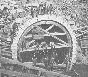
West portal of the Hoosac Tunnel, centering placement of finished stonework, 1874.
Hoosac Tunnel
Hoosac Tunnel: northwest Massachusetts, 1851 – 1875. This railroad tunnel led to many advances in hard rock tunneling. When the tunnel project started they were blasting with black powder. By the end of the project they were using the far more powerful nitroglycerine. Multiple mechanical drilling machines were invented and employed. But final success came with Charles Burleigh’s pneumatic drill. The author credits the air powered drill developed for the Hoosac tunnel as the dawn of modern rock tunneling.
Thames Tunnel
Brunel’s Thames Tunnel: under the Thames River in London, 1835 – 1843. This was the first successful subaqueous tunnel under a river. An elaborate shield was established at the tunnel face consisting of numerous planks pushed up against the soft ground. The shield was propelled forward by screws as tunnel excavation continued. The Thames River broke through the top of the tunnel on occasion flooding the project. The break would have to be filled from above and inspected by a man in a diving bell. The diving bell experience would lead to another application in subaqueous tunneling in the future.
Tower Subway Tunnel
Tower Subway: under the Thames River in London, 1869. Engineered by James Henry Greathead, the Tower Subway was smaller than the Thames Tunnel and was meant for rail cars as opposed to foot traffic of the Thames Tunnel. It was also built further below the river bottom and used a circular tunneling face instead of the rectangular shield of the Thames Tunnel. The circular shield engineered by Peter Barlow was,
…like the cap of a telescope with a sharpened circular ring on the front to assist in penetrating the ground. The diaphragm functioned, as did Brunel’s breasting board, to resist the longitudinal earth pressure of the face, and the cylindrical portion behind the diaphragm bore the radial pressure of roof and walls. – page 221
Beach’s Broadway Subway Tunnel
Beach’s Broadway Subway, under Broadway, New York, 1869. This tunnel was built in secret at night to avoid opposition from local political bosses. The tunnel looked and was engineered very similar to the Tower Subway Tunnel. The short tunnel of 312 was designed to move a subway car propelled by air pressure alone. The line, which opened in 1870, was in operation for one year. The Beach Tunnel used a shield that was driven into the soft ground and then the dirt removed. No excavation took place in front of the shield like most other tunnel projects.
Hudson River Tunnel
Hudson River Tunnel, under the Hudson River between Hoboken, N.J. and New York, 1873 – 1904. Similar to the air pumped into the diving bell used on the Thames Tunnel kept the water out of the bell, air pressure was applied to the actual subaqueous tunnel project under the Hudson River. The workers had to go through a decompression air lock to acclimate their bodies to the differential in air pressure.
The basic scheme was workable, but in operation an extreme precision was required in regulation the air pressure in the work area. It was soon found that there existed an 11-psi difference between the pressure of the water on the top and the bottom of the working face, due to the 22-foot height of the unlined opening. Thus it was impossible to maintain a perfect pneumatic balance of the external pressure of the entire face. – page 234
The positive air pressure kept the water out of the Hudson tunnel and kept the working face from slumping. Because the tunnel excavation didn’t need to rely on a system of planks to hold dirt in place, tunnel construction was greatly sped up.
St. Clair Tunnel

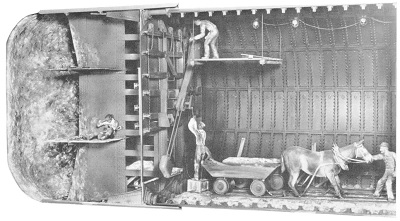
St. Clair tunnel shield, rear view showing erector arm placing cast-iron lining segment. The tree motions of the arm – axial, radial and rotational, were manually powered, scaled model. Smithsonian photo 49260-C
St. Clair Tunnel, under the St. Clair River, Sarinia, Ontario, Canada, 1886 – 1890. Despite a relatively slow start because of unforeseen soil conditions, once the St. Clair Tunnel got going it was progressing at a rate of 455 feet per month. The St. Clair Tunnel integrated all the best engineering of previous subaqueous tunnels from a circular shield to pressurized tunnel face. In addition, “Here, for the first time, an “erector arm” was used for the placing the segments, which weighed about half a ton.” – page 238
Historic photographs, drawings, scaled models
There are numerous historic photographs, pictures of the scaled models, and line drawings throughout the booklet.
- Hoosac Tunnel: blast holes drilled by hand – model.
- Hoosac Tunnel: working with Burleigh pneumatic drills mounted on carriages – model.
- Hoosac Tunnel: bottom of central shaft showing elevator car and rock skip – model.
- Burleigh rock drill, 1876, line drawing.
- Hoosac Tunnel: flash powder photography of Burleigh drill.
- Hoosac Tunnel: group of miners descending in west shaft – photograph.
- Hoosac Tunnel: engravings of construction work in the tunnel, 1873.
- Hoosac Tunnel: nitroglycerine blast, illustration, 1873.
- Hoosac Tunnel: survey crew at engineering office – photograph.
- Hoosac Tunnel: hoisting, pumping and air compressor building, 1871 – photograph.
- Hoosac Tunnel: air-compressor building on the Hoosac River – photograph.
- Hoosac Tunnel: west portal before completion, 1868 – photograph.
- Hoosac Tunnel: centering for placement of finished stonework at west portal, 1874 – photograph.
- Hoosac Tunnel: advertisement for the west portal completion and railroad passenger, 1876 – illustration.
- Soft ground tunneling, 16th century – model.
- Soft ground tunneling, 16th century – engraving.
- Austrian system of timbering 19th century railroad tunnels – model.
- Brunel’s Thames Tunnel – model.
- Brunel’s Thames Tunnel, enlarged detail of shield and vertical section with brick lining – model.
- Thames Tunnel: advertisement and map – engraving.
- Brunel’s Thames Tunnel: vertical section of shield – line drawing.
- Thames Tunnel: section through riverbed following break – illustration.
- Thames Tunnel: transverse section through shield after inundation of river – illustration.
- Thames Tunnel: longitudinal section through Thames Tunnel as sandbagging to close break – illustration.
- Thames Tunnel: interior of the tunnel shortly after opening, 1843 – illustration.
- Thames Tunnel: in use by the London Underground railway, 1869 – engraving.
- Tower Subway: placing segments of cast iron lining – model.
- Tower Subway: advancing the tunnel, workers, putting up the castings, 1869 – engraving.
- Tower Subway: excavation in front of the shield – model.
- Tower Subway: interior of completed tunnel, 1887 – engraving.
- Beach’s Broadway Subway: advancing the shield with hydraulic rams, 1869 – model.
- Beach’s Broadway Subway: vertical section through shield, horizontal shelves, iron cutting ring, hydraulic rams – engraving.
- Beach’s Broadway Subway: interior of finish tunnel showing lining for pneumatically powered passenger car.
- Beach’s Broadway Subway: giant roots lobe-type blower used for propelling the cars – engraving.
- Beach’s Broadway Subway: testing alignment of tunnel with rod to street surface – engraving.
- Hudson Tunnel: Haskin’s pneumatically driven tunnel under the Hudson River, 1880 – model.
- Hudson Tunnel: men escaping a breach and running into the air lock – engraving.
- Hudson Tunnel: map of Hoboken, N.J. and New York where tunnel went under the Hudson River – engraving.
- St. Clair Tunnel: showing erector arm placing cast iron lining into tunnel walls.
- St. Clair Tunnel: opening of the tunnel under the St. Clair River, 1891 – photograph.
Tunnel Engineering – A Museum Treatment
Download the PDF: [wpfilebase tag=fileurl id=628 linktext=’Tunnel Engineering – A Museum Treatment’ /]